16 Results
View results:
Sort by:

In RFEM 6, the results for the FE mesh nodes are determined using the finite element method. For the distribution of internal forces, deformations, and stresses to be continuous, these nodal values are smoothed through an interpolation process. This article will introduce and compare the different types of smoothing that you can use for this purpose.

This article shows you the internal forces and displacements of a continuous beam calculated both with and without consideration of shear stiffness.

Inserting holes in surfaces is very easy due to the large selection of tools. In order to insert holes or drilling in solids, it is necessary to keep in mind that an opening at the beginning and the end of a continuous hole must be created, as well as a surface that separates the hole from the solids.
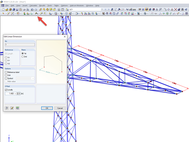
In RFEM and RSTAB, you can have contiguous dimension lines that are inclined in space.
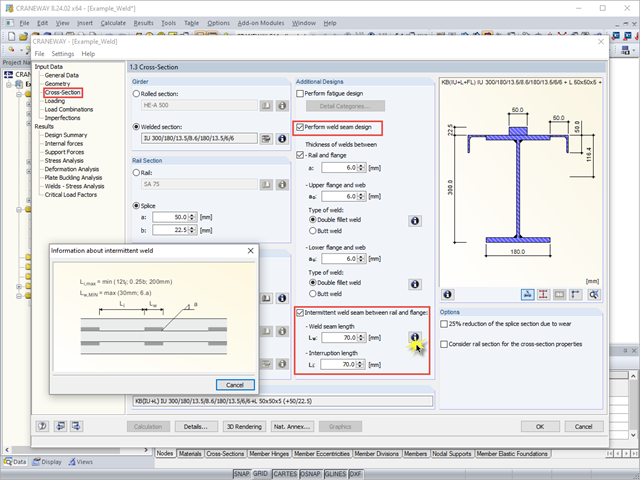
When using interrupted welds between the rail and flange, make sure that the applied weld length does not exceed the length of the rigid load application of the wheel load according to Equation 6.1 in [1].

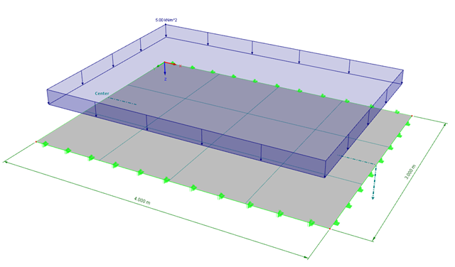
According to Book 631 of the DAfStb (German Committee for Structural Concrete), Chapter 2.4, the structural behavior of ceilings changes if their continuous support by walls is interrupted in areas of openings. Depending on the length of the opening area and the plate thickness, measures are necessary regarding the analysis of the ceiling in the area of the opening.
When calculating a surface model, the internal forces are determined separately for each finite element. Since the element-by-element results usually represent a discontinuous distribution, RFEM performs smoothing of the internal forces that takes into account the influence of adjacent elements. The discontinuous distribution of internal forces is adjusted with this method. The result evaluation is thus clearer and easier.
.png?mw=640&hash=1be9a846b1f57190540c7fc7f46f44cd40ab7029)
The calculation of structures based on digital twins is becoming an everyday task in the engineering office. If a digital building model already exists, you want to continue to use the information contained in it as seamlessly as possible. This states extensive requirements with regard to modeling and interfaces for BIM-compatible structural analysis software.
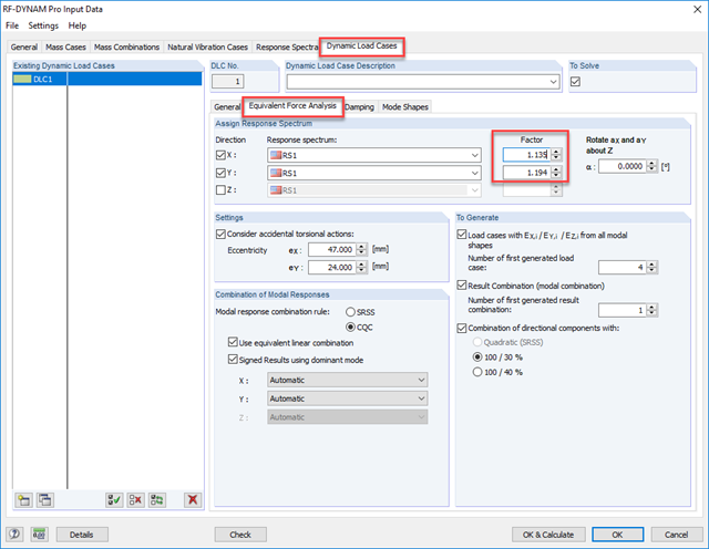
As gravity loads act on a structure, lateral displacement occurs. In turn, a secondary overturning moment is generated as the gravity load continues to act on the elements in the laterally displaced position. This effect is also known as "P-Delta (Δ)". Sec. 12.9.1.6 of the ASCE 7-16 Standard and the NBC 2015 Commentary specify when P-Delta effects should be considered during a modal response spectrum analysis.
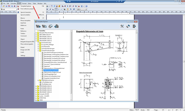
An interface can be used to export the RFEM/RSTAB printout report to VCmaster and continue editing there. VCmaster is a word processing program for engineers.
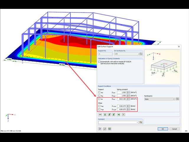
A previous article presented different variants of surface elastic foundations in addition to the traditional subgrade reaction modulus method. The following article describes another method for surface foundation. This method considers the adjacent ground areas by means of a foundation overlap. In this case, foundation parameters refer to the continuing works by Pasternak and Barwaschow.
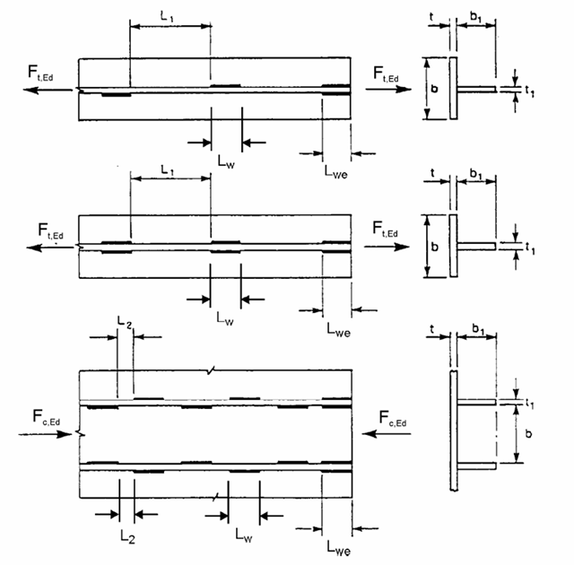
If crane runway girders are designed with flat steel rails, the welding of these rails is always a detail for the design. You can generally select between continuous and intermittent fillet welds as a rail fixing. The following article provides an overview of the design processes and their specific features, especially when using the EN 1993-6.
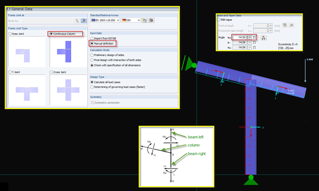
Since no automated frame joints of the "continuous beam" type are included in RF‑/FRAME‑JOINT Pro, you can use another option for designing this type. Designing this kind of beam combination is possible using manual definition and the "Continuous Column" type.
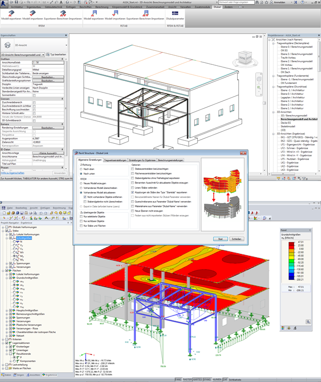
The increasing use of the BIM method in planning buildings also opens up new possibilities for structural engineers. Once a comprehensive 3D model of a building has been created, you want to continue using it for the structural analysis and gain the maximum benefit from it. However, there are also some new challenges for the structural engineer and the software used, which are described in this article.
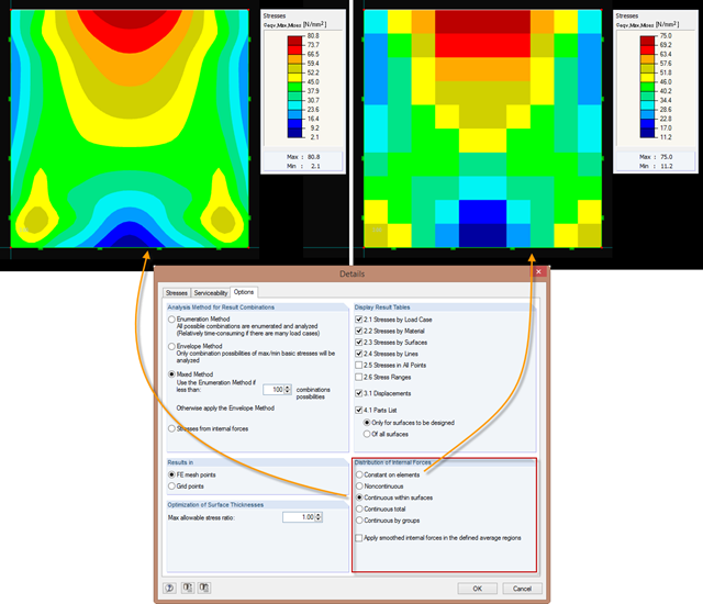
Just as in the RFEM Display Navigator, you can set the distribution of internal forces in surfaces in RF‑STEEL Surfaces. Since deformations are always the result of the FEM calculation, the corresponding forces will be recalculated. This means that the internal forces on an FEM element are calculated depending on the composition (triangular or square) in three or four places. In order to obtain continuous internal forces and thus a smoothed distribution, these internal forces have to be interpolated. Interpolation is done by selecting the "Distribution of internal forces" option in the surfaces.
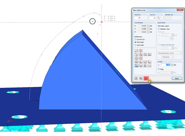
In RFEM, if you want to display a curved geometry (preferably in one continuous line), you can use splines or NURBS, for example. When modeling, you should pick the individual nodes one after another. If a mistake is made, you can go back using the special Undo function in the "New Spline Line" window. Thus, it is not necessary to enter the entire continuous line again.